lab08 : Finite State Machines
| num | ready? | description | assigned | due |
|---|---|---|---|---|
| lab08 | true | Finite State Machines | Thu 03/07 08:00AM | Wed 03/13 11:59PM |
Lab 8: Finite State Machines
Due Wednesday, March 13th at 11:59:59 PM
Goals for This Week
By the time you have completed this work, you should be able to:
- Draw a finite state diagram corresponding to a basic word problem
- Demonstrate your ability to implement this state diagram via a circuit
Provided files:
Step by Step Instructions
For this week, you will translate a word problem into a diagram representing a finite state machine (FSM). From there, you will provide enough detail to implement the finite state machine as a circuit. There are multiple tasks for this assignment. While each task can be completed independently of each other, they progressively build in difficulty, so it is recommended to complete them in order. The tasks are listed below:
- Task 1: Design a FSM For a Digital Display
- Task 2: Design a FSM to Recognize
0110
The initial step below describes how to get the files you will need into the appropriate place. These files are used for all the different tasks.
Task 1: Design a FSM For a Digital Display
In this task, you will design a FSM which controls a seven segment display. Throughout this task, we will be using a seven segment display similar to the following (provided by Wikipedia):
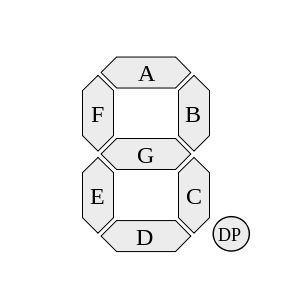
Each of the letters in the above diagram refers to an individual segment of the display.
The identifier “DP” refers to the decimal point, which will not be used in this task.
The display allows segments to be individiually turned on and off, allowing for different numbers to be represented by selectively enabling or disabling the right segments.
The table below illustrates which segments need to be enabled for the corresponding decimal digit to be represented:
| Number | Segments to Enable |
|---|---|
0 |
A, B, C, D, E, F |
1 |
B, C |
2 |
A, B, G, E, D |
3 |
A, B, G, C, D |
4 |
F, B, G, C |
5 |
A, F, G, C, D |
6 |
A, F, G, E, C, D |
7 |
A, B, C |
8 |
A, B, C, D, E, F, G |
9 |
A, B, C, D, F, G |
The FSM for this task should alternate between displaying 1, 2, 4, and 8, in that order, and without the application of any external input (in other words, you go from one state to another on just the "tick" of the clock).
In order to accomplish this, the inputs to the seven segment display will be treated as outputs of your FSM.
That is, your FSM will output the appropriate values of A, B, C, D, E, F, and G in order to represent the numbers of interest.
This overall task is separated into a series of questions, which should be submitted digitally via the turnin command.
-
Draw the finite state machine corresponding to this task.
-
How many latches/flip-flops do you need to implement this state machine? (Hint: this corresponds to the number of bits necessary in order to encode all possible states uniquely.)
-
Draw a single truth table representing the behavior of the state machine. Be sure to label your states in binary. Your table should have inputs corresponding to whatever state you are in. The output corresponds to the next state to enter for a given input state, along with the values for the seven segment display.
-
Using a Karnaugh map, determine the minimal sum-of-products formula corresponding to output
A(corresponding to inputAof the seven-segment display. Where appropriate, use don't cares in the map (note that there may be no appropriate uses of don't cares). -
Using a Karnaugh map, determine the minimal sum-of-products formula corresponding to the rightmost bit of the next state. Where appropriate, use don't cares in the map (note that there may be no appropriate uses of don't cares).
To help with questions 1-3, a solution to a very similar problem is provided here.
In this example, the FSM alternates between displaying 1 and 7.
The diagram has these major components:
-
Circles, representing the different states of the FSM.
These are written in black.
Each state has the following information written on it:
-
A human-readable label, written in purple.
The labels chosen for this example correspond to whether the state displays a
1or a7. - A binary label, shown in parentheses and written in green. Each state needs a unique binary label, which is used in the truth table (shown in red at the bottom of the image).
-
The output of the state, underlined and written in blue.
For example, in state
7(binary1), the output of the state isABC, meaning segmentsA,B, andCin the seven-segment display should be activated. In conjunction, when these three segments are lit up, they display7.
-
A human-readable label, written in purple.
The labels chosen for this example correspond to whether the state displays a
- Arrows, representing transitions between different states of the FSM. Transitions occur on clock ticks, which are provided by an unseen (but implicitly present) clock.
Task 2: Design a FSM to Recognize 0110
In this task, you will design a FSM which will set a particular output U to 1 each time 0110 is encountered in a stream of inputs.
Inputs are specified one at a time, and are represented by the variable I.
To illustrate, consider the following example, which shows different values of U and I over time, where each cell is separated by a clock tick:
I |
1 |
0 |
1 |
1 |
0 |
0 |
1 |
1 |
0 |
1 |
0 |
1 |
1 |
0 |
1 |
1 |
0 |
1 |
1 |
0 |
1 |
U |
0 |
0 |
0 |
0 |
0 |
1 |
0 |
0 |
0 |
1 |
0 |
0 |
0 |
0 |
1 |
0 |
0 |
1 |
0 |
0 |
1 |
In the above example, it may appear that the output of U is delayed with respect to input I.
That is, when the 1 is 0110 is encountered, it's not until the next clock tick that U is set to 1.
This is actually expected behavior, as it reflects the fact that first the circuit reads 1, and then it moves into a state that reports U = 1.
This overall task is separated into a series of questions, which will be submitted digitally via turnin as 3 files (sequence.txt, sequence1.jpg OR .pdf, and sequence2.jpg OR .pdf):
-
Draw the finite state machine corresponding to this task. Put this state diagram into a file named “
sequence1.jpg” and put the circuit drawing into a file named “sequence2.jpg”. You may instead turn in sequence1 and sequence2 as scans in PDF format (instead of a JPEG picture). -
How many latches/flip-flops do you need to implement this state machine? (Hint: this corresponds to the number of bits necessary in order to encode all possible states uniquely.)
-
Draw a single truth table representing the behavior of the state machine. Be sure to label your states in binary. Your table should have inputs corresponding to whatever state you are in, along with
I. The output corresponds to the next state to enter for a given input state, along withU. -
Using a Karnaugh map, determine the minimal sum-of-products formula corresponding to output
U. Where appropriate, use don't cares in the map (note that there may be no appropriate uses of don't cares). -
Using a Karnaugh map, determine the minimal sum-of-products formula corresponding to the rightmost bit of the next state. Where appropriate, use don't cares in the map (note that there may be no appropriate uses of don't cares).
-
Based on your findings, draw the FSM circuit using D-FFs and combinatorial logic. Make sure you CLEARLY label this diagram.
Pay particularly close attention to where transitions should go which move “backwards” in the FSM. That is, it is expected that you'll have transitions which go to previously observed states, and these transitions won't necessarily all return to the same state.
Again, put all the information in the sequence.txt file, the picture (or scan) of the state diagram in sequence1.jpg (or sequence1.pdf, if scanning), and the picture of the circuit in sequence2.jpg (or sequence2.pdf, if scanning).
Turn in Everything AS A PAPER COPY!!!!
You will do this lab entirely on paper (old school rules!!) and turn in your assignment at the CS64 BOX in the Computer Science department mail room (next door to the CS Dpt. Office) on the 2nd floor of HFH.
Your submission MUST be WRITTEN/DRAWN NEATLY and STAPLED together. Please ensure that your name (and your partner's name, if you have one) is on EVERY PAGE OF THE ASSIGNMENT!
Copyright 2018, Ziad Matni, CS Dept, UC Santa Barbara. Adapted from work by Diana Franklin and Kyle Dewey. Permission to copy for non-commercial, non-profit, educational purposes granted, provided appropriate credit is given; all other rights reserved.